
The data chain fails at one link, and everything after starves
An RGBIC strip is a chain of ICs playing pass-the-message. Power runs the full length on its own rails, but color data enters at the controller end and is regenerated chip by chip. One dead or corrupted chip stops the message: LEDs before it work perfectly, everything after shows dark, frozen, or garbage colors — while still receiving power. This is why the boundary between good and bad is the only place worth inspecting.
Before fault-hunting, rule out a configuration cause: a controller set for fewer pixels than the strip carries will darken the tail with nothing broken. If the dark section starts suspiciously at a round number — half the strip, or exactly where an extension was added — check the app's pixel-count setting first.
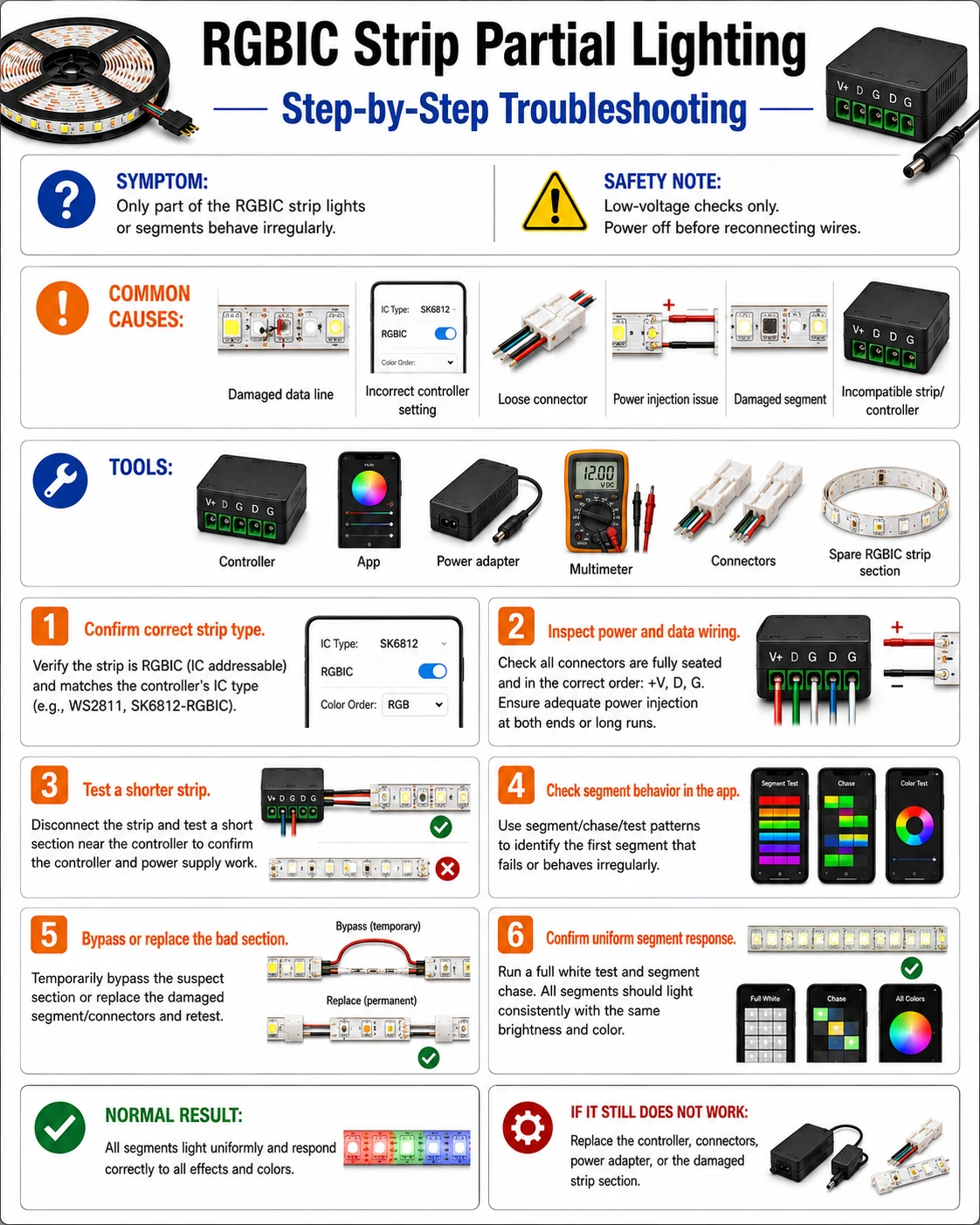
Prepare before testing
- The controller app with pixel-count settings — misconfigured length mimics a hardware fault exactly
- Multimeter — to verify supply voltage is present in the dark zone — proving it is data, not power
- Sharp scissors and a spare matching segment — the repair is cut-and-splice around the failed chip
- Magnifier — the failed chip's solder or a cracked data trace at a flex point is small
Match replacement segments exactly — same voltage and same IC family. A WS2812 segment spliced into an SK6812 run powers up but speaks a different dialect and corrupts everything downstream.
Check these areas first
- Failed IC at the boundary. the last working pixel's neighbor has died and stopped forwarding data
- Cracked data trace at a bend. power traces survive flexing longer than the thinner data trace; the strip lights but data stops at the crack
- Bad splice after a previous repair. data pad misaligned or arrows opposed at a joint — power crosses, data does not
- Pixel count set too low. the controller simply never addresses the tail; common after mixing strips or app reinstalls
- Missing common ground at a power injection. an injected supply whose ground does not tie back corrupts the data reference from that point on
Diagnostic procedure
Confirm power in the dark zone, clear the configuration suspects, then close in on the boundary chip — the sequence avoids cutting a strip that only needed a settings change.
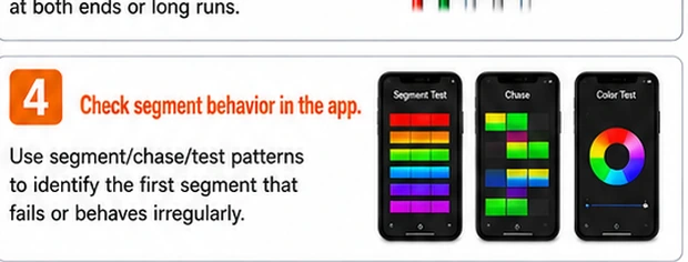
Run a full-strip solid color test
Command a static single color at full brightness. Note exactly which pixel is the last to behave and whether the zone after it is dark, frozen on old colors, or flickering garbage. Dark suggests no data at all; garbage suggests corrupted data — a ground or dialect problem rather than a dead chip.
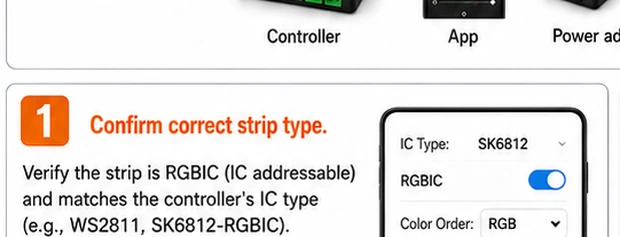
Verify the controller's pixel count
In the app, compare the configured LED count against the strip's real count (count segments, or check the spec — commonly 30, 60 or 144 per meter). Set it to at least the physical count and retest. If the tail springs to life, the strip was never broken.
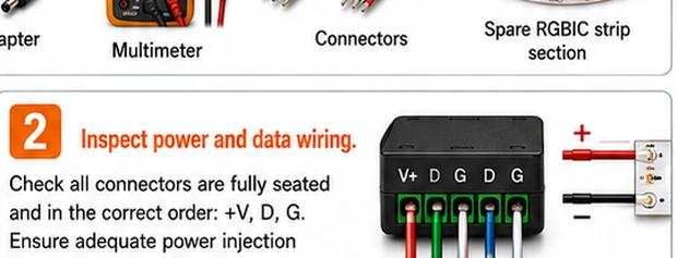
Confirm data direction across every joint
Follow the printed arrows from controller to tail. At every splice or connector, arrows on both sides must point away from the controller. A section installed backwards — easy to do with symmetric clip connectors — receives power yet blocks data permanently.
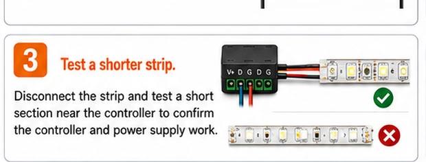
Prove power is present in the dark zone
Measure between + and – pads at a cut line inside the dark section. Supply voltage present confirms a pure data fault at the boundary. Voltage absent means this is actually a power break — a different fault with the same look; trace the power joint instead.
Inspect the boundary chip and its joints
Examine the last working pixel and its immediate neighbor: heat-browned chip body, a hairline crack across the data trace where the strip bends, corrosion under a nearby joint. Press gently on the suspect chip while running — data returning under pressure convicts that chip or its solder.
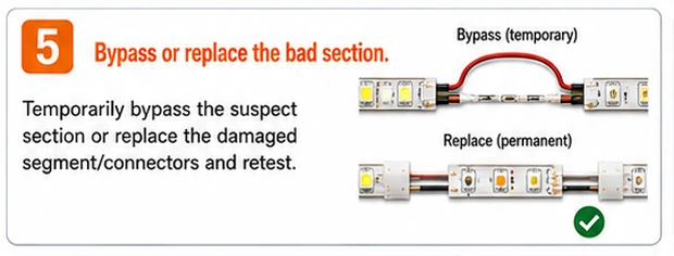
Cut out the failed pixel and splice
Power off and cut at the marked lines either side of the bad chip, removing the shortest possible piece. Splice in a matching segment — same voltage, same IC type, arrows aligned — soldering power, data and ground pad-to-pad. Retest with an animation that traverses the joint.

Why 'matching segment' is strict on addressable strips
Analog RGB strips tolerate generous substitution; addressable strips do not. IC families — WS2812B, WS2815, SK6812 and their variants — differ in timing, voltage, color order and whether they carry a backup data line. A spliced-in segment from the wrong family can appear to work at power-on and then scramble colors under animation. Buy repair stock of the exact model when you buy the strip; a one-meter spare in a drawer converts every future chip failure into a ten-minute splice.
One chip is a splice; three chips is a warning
A single dead IC in an otherwise healthy strip is normal attrition and worth the splice. Repeated failures at different points — especially with heat discoloration — mean the strip runs too hot or too hard: check that brightness-times-length stays inside the supply's rating and that the strip is not sealed in an unventilated channel. Fix the environment, or the next chip is already queued.