
Nothing is broken — the channels are shuffled
An RGB strip has one shared power rail and three return channels. The controller lights 'red' by switching whichever wire sits on its R output — if that wire physically leads to the green channel, every red command comes out green, with perfect brightness. Wrong-color faults with full brightness and all colors present are therefore wiring-order faults, not electrical ones.
Two genuinely different problems hide behind similar symptoms and are worth separating early: if one primary color never appears at all in any test (whites look wrong, too), that is a dead channel, not a shuffle — covered in the last step. And if colors are wrong only on part of the strip, that is a splice error at a joint, not a controller-end issue.
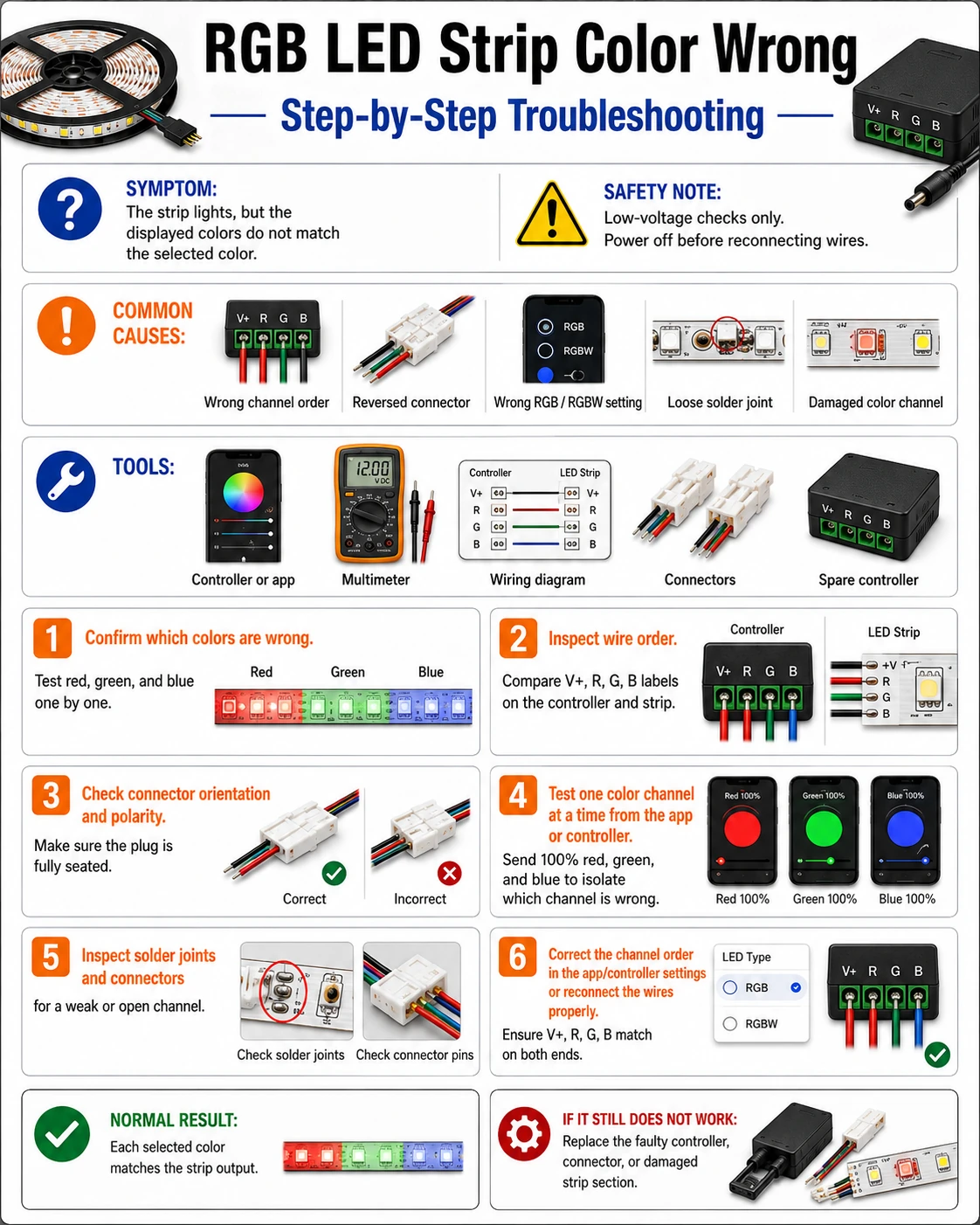
Prepare before testing
- The controller's remote or app — you need to command exact pure colors — red, then green, then blue
- Small flat screwdriver — for lifting the lock bar on 4-pin push connectors and re-seating the strip
- Paper and pen — a three-line mapping table beats memory — commanded color versus displayed color
- Multimeter (only for the dead-channel case) — to probe a channel that never lights
This is a low-voltage, low-risk job. Just disconnect power before unplugging or rotating any connector — hot-plugging a 4-pin header can momentarily short adjacent pins.
Check these areas first
- Strip inserted one pin off or rotated. 4-pin clip connectors accept the strip slightly misaligned, shifting every channel by one position
- Non-standard strip pinout. most strips run +12 V, R, G, B in order, but some vendors ship G-R-B; controller and strip disagree
- Extension cable crossed. four-wire extension leads with unkeyed plugs are easy to connect rotated at one end
- Splice with swapped wires. hand-soldered joints mid-run recolor everything downstream of the joint
- App channel-order setting changed. many controllers store an RGB/GRB/BRG order option that gets toggled accidentally
Diagnostic procedure
Build the mapping first. Every fix — connector, cable or app — needs the same three observations, so take them once and carefully.
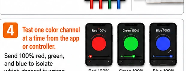
Command pure red, then green, then blue
From the remote or app, select 100% red and write down what the strip actually shows. Repeat for pure green, then pure blue. You now have a three-line table such as R→G, G→B, B→R. A consistent shuffle across all three confirms a mapping fault; a color that shows dim or dead sends you to step six.
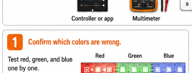
Find where the order breaks
Work through the chain: strip-to-connector, any extension leads, and the controller output header. At each junction compare the strip's printed pad labels (+12 V/R/G/B) against the wire colors or pin labels arriving there. The junction where labels stop matching is your fault point — typically the first clip connector.
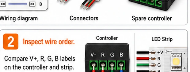
Fix the order in software if the hardware is sealed
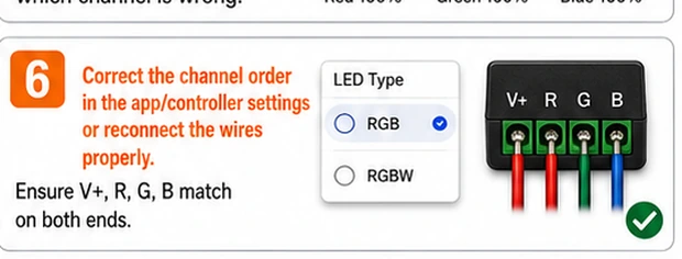
If the mismatch is inside a molded plug or you simply prefer not to rewire: most app-controlled units have a channel-order setting (RGB, GRB, BGR…). Step through the options while displaying pure red until red shows red, then verify green and blue. This is a legitimate permanent fix, not a workaround.
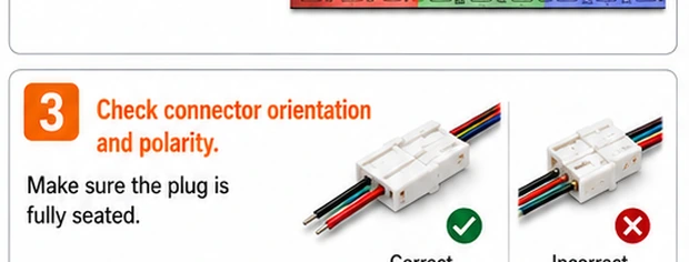
Re-seat the four-pin connections correctly
For a hardware fix: power off, open the clip connector's lock bar, and re-insert the strip with its +12 V pad aligned to the connector's marked 12 V pin — the arrow or triangle on most plugs. Check any extension lead is pinned identically at both ends. Close, power on, and re-run the three-color test.
Check any mid-run splices if part of the strip is wrong
When colors are correct near the controller but wrong past a soldered joint, the joint's wires are crossed. Power off and re-solder the joint matching pad labels on both sides — R to R, G to G, B to B. Downstream color order always inherits from the last joint.
Chase a channel that never lights
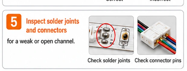
If one primary is missing everywhere (and whites look tinted), command that color and measure between +12 V and that channel's pad at the strip head. Near-supply voltage with no light means the strip's channel is open — often one cracked joint. No voltage means the controller's output transistor for that channel has died; replace the controller.
Unkeyed connectors and vendor pinouts
The 4-pin ecosystem predates any real standard: the plugs are symmetric enough to seat rotated, vendors disagree on channel order, and nothing electrical prevents a shuffled connection from powering up happily. That is also why the fault so often appears right after an install, an extension, or a controller upgrade — the parts are fine, and only the agreement between them broke. Keeping one photographed reference of a correct junction makes every future reassembly a ten-second job.