
Why one bead matters, and why the board fights back
LED boards wire beads in series strings: the same current threads every bead, so one open bead breaks its entire string — a dark row on a panel, a dead quadrant on a floodlight. The economics are stark: the bead costs pennies, the board tens, the fixture more; the only question is whether the repair's difficulty fits your equipment and patience. This guide assumes a basic iron or hot-air source, and honesty about the first attempt happening on scrap.
The board is the adversary: aluminum-core construction exists to pull heat away from beads in service, and it pulls soldering heat away just as efficiently. Cold joints from underheated pads, lifted pads from overstaying, and cooked neighbors from spillover are the three classic failures — all managed by preheating the board and working decisively rather than long.
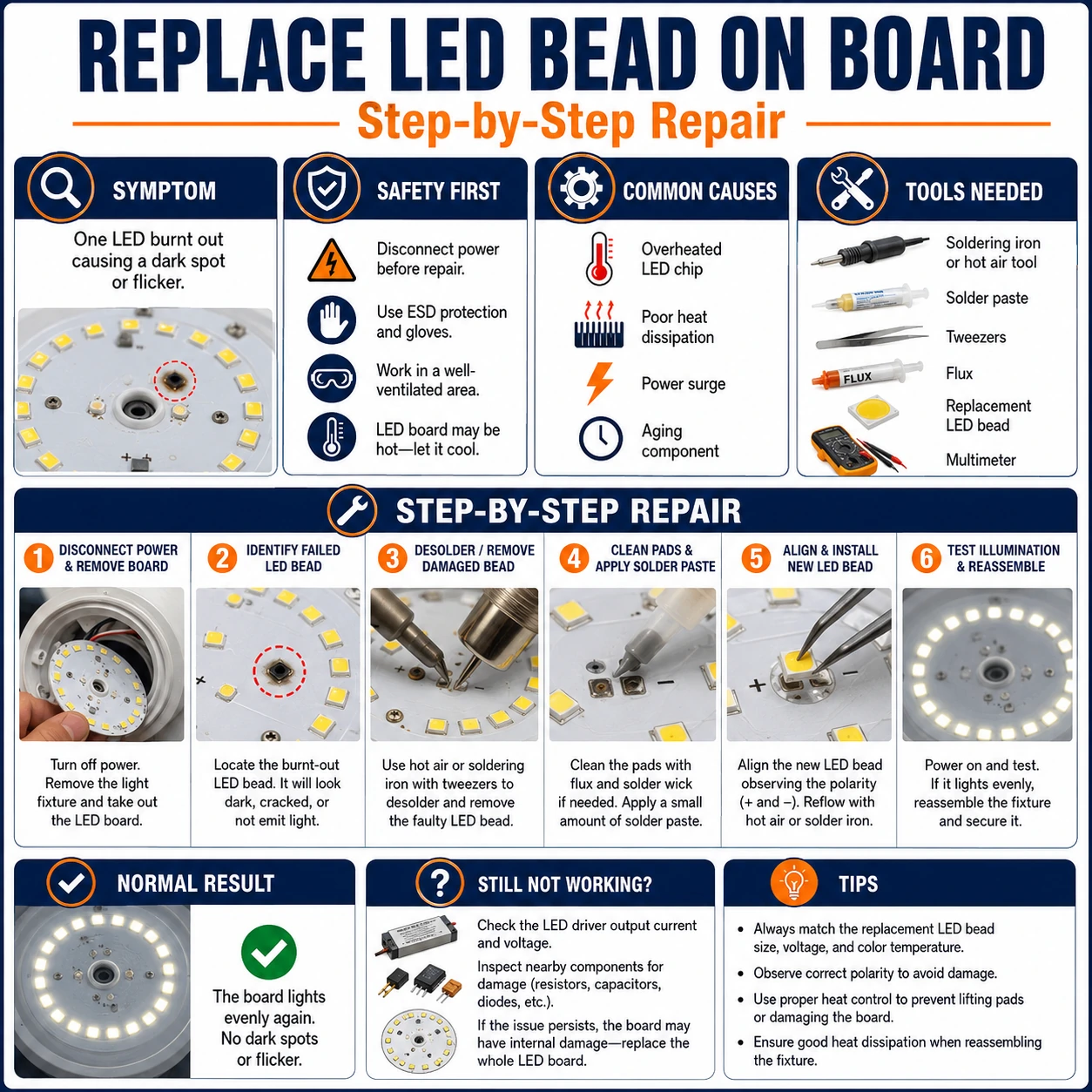
Prepare before testing
- Multimeter with diode mode — the bead-by-bead test that finds the corpse among the innocent
- Hot-air rework tool, or an iron with a wide tip — aluminum boards demand more heat delivery than pencil tips supply
- A preheating method — a hotplate, or patience with the air tool — the board at 100 °C+ makes every joint easier
- Exact replacement beads — matching package size, forward voltage, wattage and color temperature — buy several
- Flux, solder, tweezers, magnifier — the standard micro-soldering kit; flux is not optional on these pads
Power off and capacitors given time to bleed before touching the board. Hot boards look identical to cold ones — treat the whole plate as hot during and after work. Ventilate flux fumes, and keep the diode-mode test's limits in mind: some high-voltage multi-chip beads need more than a meter can push and test dark even when alive.
Check these areas first
- One bead open, string dark. series wiring means a single failure darkens every bead sharing its current
- Scorch, crack or discoloration. visible casualties — though many dead beads look pristine
- Yellowed phosphor, shifted color. a bead failing slowly announces itself in tint before it opens
- Cracked solder under thermal cycling. sometimes the bead is fine and its joint is the open — the same repair, easier
- Board-level end of life. many casualties across strings — the finding that closes the repair economically
Diagnostic procedure
Find the corpse electrically, source its twin, manage the board's heat hunger, place with correct polarity, and prove the repair at low power before trusting it with full current.
Survey visually, then test electrically
Start with magnified inspection: scorch marks, cracked lenses, browned phosphor. Then confirm with the meter's diode mode across each bead in the dark string — healthy low-voltage beads glow faintly under the test current; the dead one reads open (no glow, no voltage drop). Mark it. Beads that test dark but look perfect: note the diode-mode limitation for multi-chip beads and cross-check against neighbors' readings.
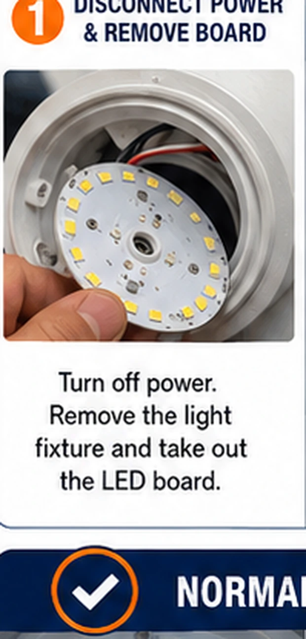
Source an exact match
Read the bead's package size (2835, 3030, 5050 and kin), and from the fixture's spec or the board's markings its forward voltage, wattage and color temperature. Order exact matches, several — the first may be spent learning, and future failures on this board will want the same stock. A near-match in voltage unbalances the string; a mismatch in color temperature makes the repair visible forever.
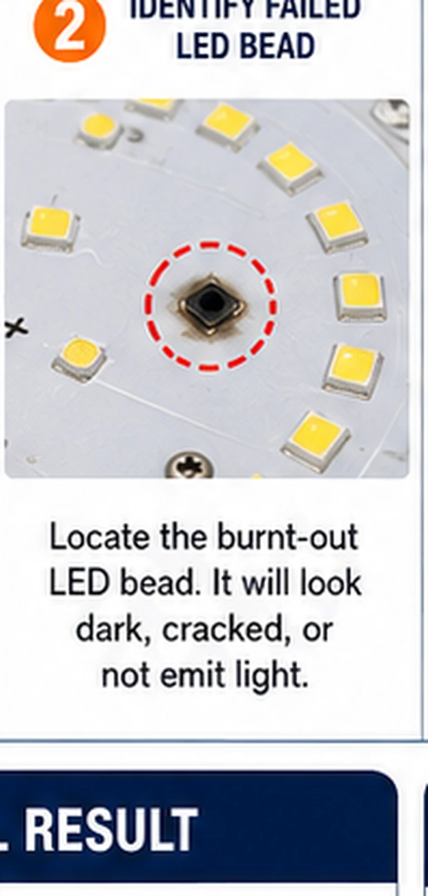
Preheat the board
Set the board on a hotplate or warm it broadly with the air tool until it is uncomfortably warm to a quick touch. Aluminum-core boards sink soldering heat so effectively that pad-level work on a cold board means either failure or dangerous dwell times. Preheating is the single technique separating clean bead swaps from lifted pads.
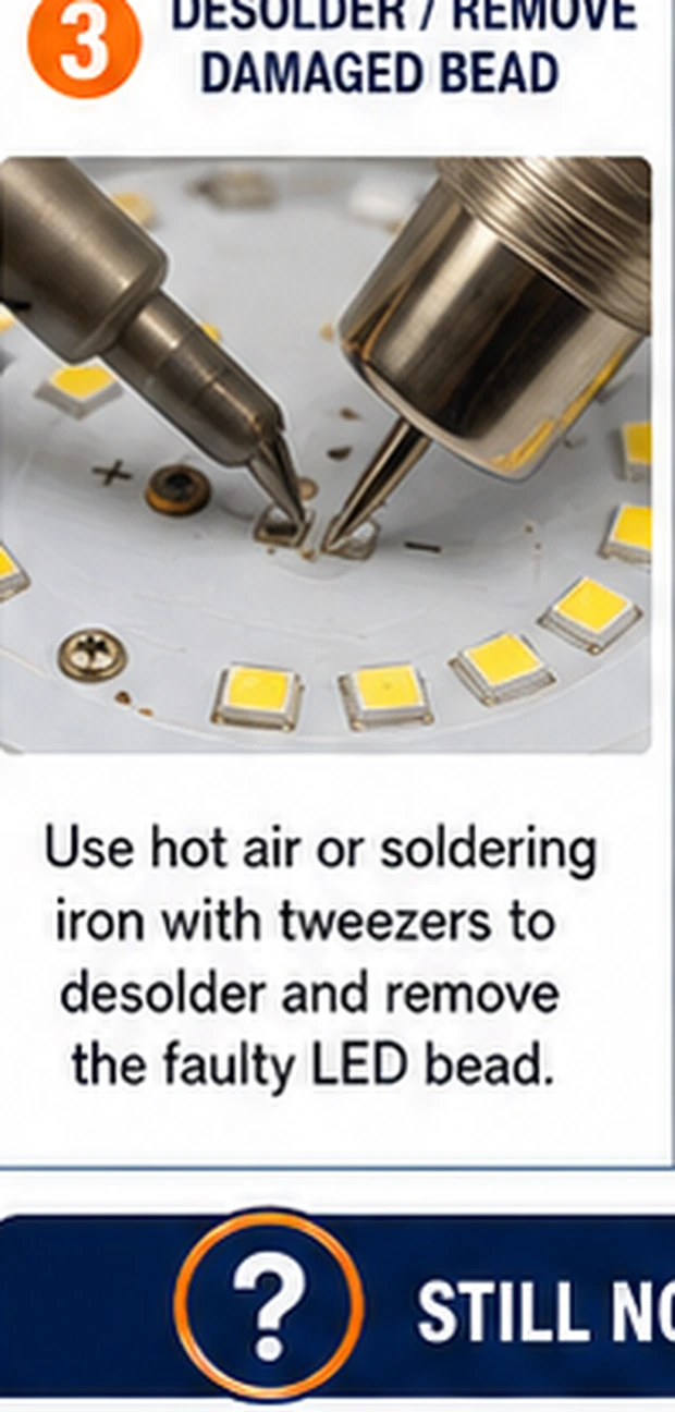
Remove the dead bead cleanly
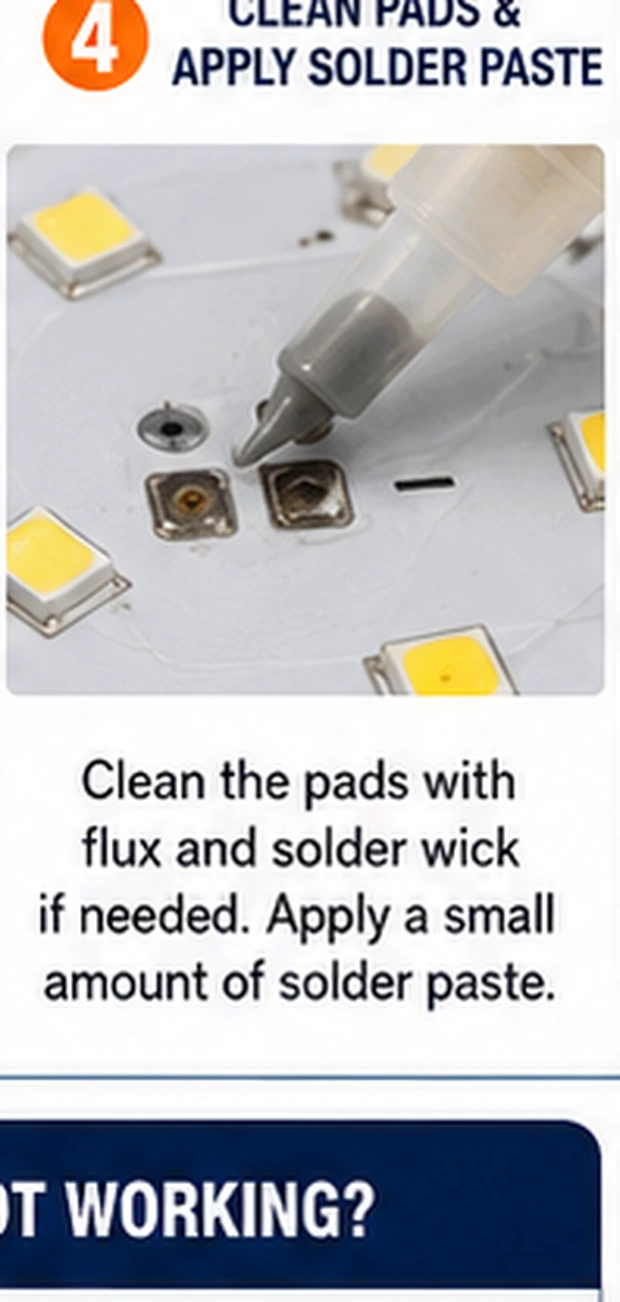
With hot air aimed tightly (or a wide iron tip bridging both pads), heat until the solder releases and lift the bead with tweezers — seconds on a preheated board. Resist prying: pads tear before solder yields when underheated. Clean the site with flux and a touch of fresh solder, leaving two bright, level pads.
Place the new bead with polarity certain
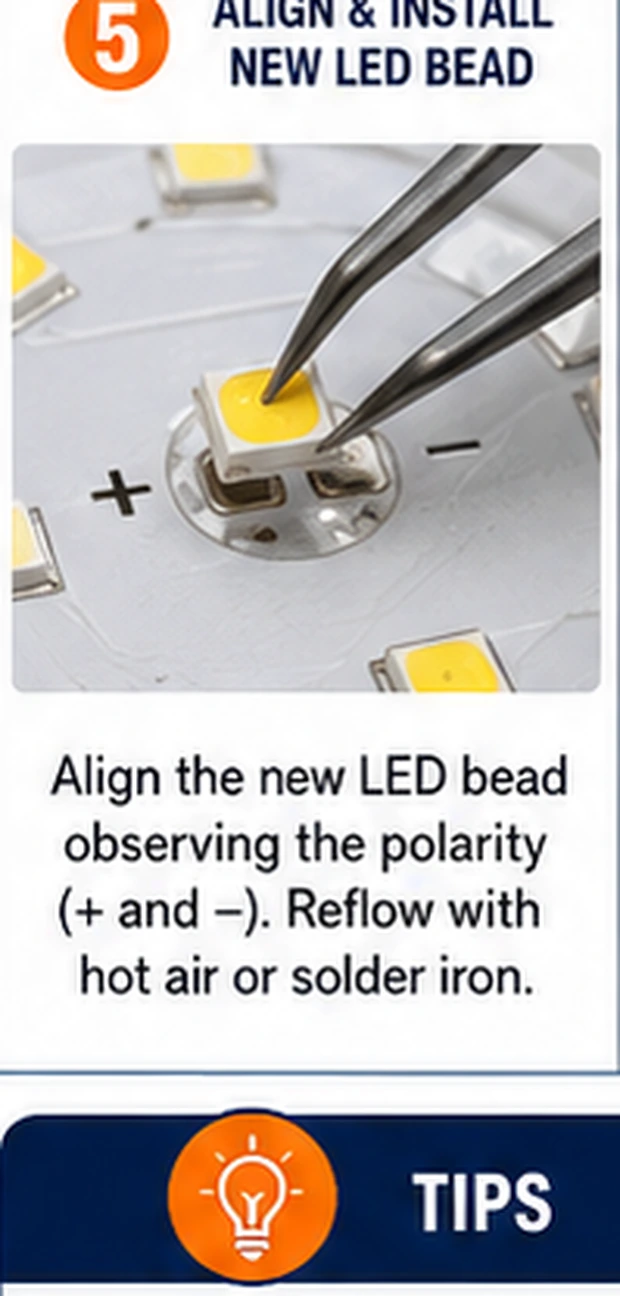
Find the polarity marks — a corner notch, a green dot, a chamfer — on both the new bead and the board's silkscreen; when the board is unmarked, photograph a neighboring bead's orientation before removal and copy it. Place, reflow briefly until the solder wets both terminations, and let the surface tension square the bead on its pads.
Verify at low power, then service
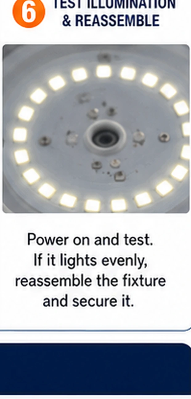
First power-up at the lowest available brightness or through a current-limited bench setup: the string should relight evenly, the new bead matching its neighbors in tint. Watch and sniff the site through several minutes; a repair that runs even and cool at low power then earns a full-brightness soak test before the fixture closes up.
The luckier version of the same fault
Thermal cycling cracks solder as readily as it kills beads, and a cracked joint under a healthy bead produces the identical dark string. The tells: diode mode reads open across the bead, but wiggling gentle probe pressure on the bead makes readings flicker — or magnification shows a hairline ring in the solder fillet. The repair is the same site work minus the sourcing: flux, reflow both pads on a preheated board, retest. Worth checking before ordering parts; a meaningful share of 'dead bead' repairs end at this cheaper diagnosis.
Board triage before the iron heats
Count the casualties before committing. One dead bead on an otherwise clean board: ideal repair. Two or three, especially with browned board zones around them: the board is running too hot in service — repair if you must, but fix the fixture's cooling or driver current, or the replacements join the queue. Casualties scattered across multiple strings, widespread discoloration, or phosphor yellowing on survivors: board-level end of life, where the honest spend is a replacement board or fixture and the beads in your drawer wait for a healthier patient.