
Three settings cover the whole hobby
Low-voltage lighting diagnosis uses a fraction of the meter's dial: DC voltage (V with a straight line) for 'is power here, and how much'; continuity (the beeper) for 'is this wire, fuse or switch a complete path'; and occasionally resistance for 'is this a short'. Everything else — AC volts, current ranges, capacitance — can wait. Competence with three settings, applied at the right points in a circuit, is the entire skill.
The discipline half is short but non-negotiable: probes in the right sockets (the 10 A current jack is the classic trap — a meter set there across a supply is a dead short through the meter), voltage measured across things while powered, continuity measured along things only when dead, and one hand's worth of attention to where both probe tips are at all times.
Prepare before testing
- A basic digital multimeter — auto-ranging preferred; the beeper (continuity) function is essential
- Its own manual, once — socket layout and symbols differ by model; ten minutes of reading prevents the classic mistakes
- Alligator-clip probe adapters (optional) — hands-free probing on strips and terminals doubles accuracy
- A notepad — readings compared beat readings remembered — every diagnosis is a series, not a number
This guide and this site confine the meter to extra-low-voltage work: adapters' DC outputs, strips, controllers, batteries. Mains measurement is a different discipline with different equipment ratings — leave the wall side to electricians. And never measure continuity or resistance on a powered circuit.
Check these areas first
- Guesswork costs parts. without measurement, diagnosis is shopping — replacing suspects until one purchase works
- Loaded versus unloaded truths. supplies that read perfect open-circuit and collapse under load fool every eye
- Invisible breaks. enamel wires and moulded cables break inside intact insulation, findable only by beeper
- Polarity mistakes. center-positive versus center-negative adapters look identical and destroy controllers
- First-point-of-failure logic. a chain of readings from supply to load names the failing link by elimination
Diagnostic procedure
Learn the sockets, then DC volts unloaded and loaded, then the beeper on dead circuits, and finally the walking-the-chain method that turns single readings into diagnoses.
Put the probes in the right sockets
Black probe to COM, always. Red probe to the V/Ω socket for everything in this guide. The separate high-current jack (10 A or similar) is only for deliberate current measurement — a meter left set there behaves as a near-short across whatever the probes touch next. Make the check-the-sockets glance a reflex whenever picking the meter up.
Select DC volts and take a first reading
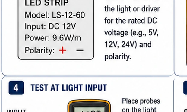
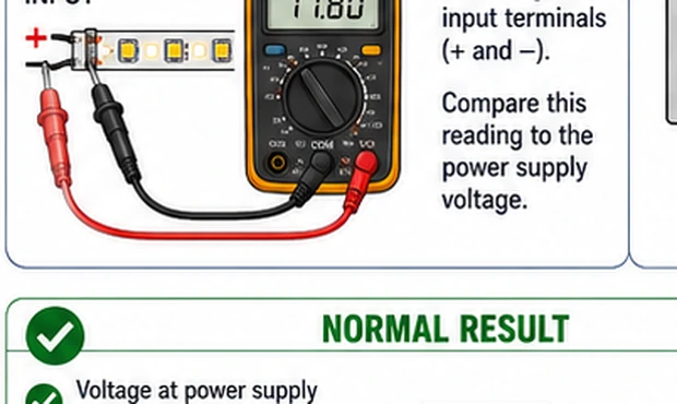
Set the dial to DC voltage (V⎓, not V~ which is AC). Auto-ranging meters need nothing more; manual meters want a range above the expected voltage — 20 V for 5/12 V systems. Practice on a battery: red to +, black to −, expect the nominal voltage; swapped probes read negative, which harms nothing and teaches polarity for free.
Measure an adapter unloaded, then loaded
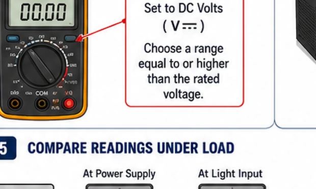
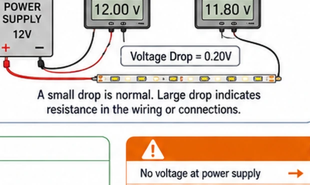
Read the adapter's output plug: red to the center pin, black to the barrel (a negative reading means the adapter is center-negative — note it, since polarity matters to controllers). Then reconnect the load and measure again at an accessible joint while the lights run at full. Healthy: both readings near the label. The failure signature: fine unloaded, collapsing under load — a supply dying, or a resistive joint upstream of the measuring point.
Use continuity only on dead circuits
Power off and disconnected. Dial to the beeper symbol, touch the probes together to hear the reference tone, then test paths: fuse ends (beep = good), each conductor of a suspect cable end to end (silence = the break), switch terminals in both positions (beep in on, silence in off). The beeper turns invisible breaks into audible facts.
Walk the chain to the first bad point
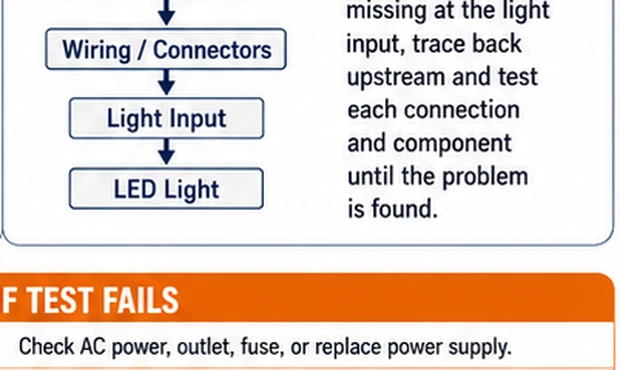
The method behind every diagnosis on this site: measure DC volts at each accessible point in order — adapter plug, controller input, controller output (color commanded), strip head, strip tail. Record each. The chain reads healthy up to the failure and wrong from it onward; the first bad reading names the segment to repair, and everything upstream is exonerated in the same pass.
Log readings against time
Date the numbers for anything that matters — the new supply's loaded voltage, the long strip's head and tail figures after installation. Faults announce themselves as drift long before failure: a tail voltage sagging season by season is a corroding joint scheduling its own repair. Comparison is the meter's quiet superpower, and it costs one notebook line per measurement.
The meter this hobby actually needs
For low-voltage lighting, modest meters are entirely sufficient: auto-ranging, DC volts, a loud continuity beeper, and a resistance mode cover every guide on this site. Features worth small premiums — a backlit display for behind-furniture work, min/max hold for catching supply dips, decent probes with removable clip adapters. Features this hobby does not need to pay for: high AC accuracy, clamp attachments, or four-digit precision. What matters more than the meter is its category rating being genuine if it will ever meet mains — and since this site's rule keeps it off mains entirely, even that concern stays theoretical.
Named so they never happen
Meter accidents in this hobby are two, both preventable by ritual. The current-jack short: probes left in the amps socket from a previous experiment, touched across a supply — the meter conducts like a wire, the supply's protection (or the meter's fuse) decides the outcome. Cured by the sockets-glance reflex. The live-continuity mistake: beeper mode on a powered circuit — the meter injects its test current into electronics that never asked for it, and readings are garbage anyway. Cured by the power-off habit bound to the beeper's use. Two glances, zero accidents, indefinitely.