
A good strip joint is quick precisely because pads are fragile
LED strip pads are thin copper on a flexible substrate. They tolerate heat for a second or two, then the adhesive under them softens and the pad lifts off with your iron — the one failure you cannot undo. Every technique below exists to shorten iron contact: clean surfaces, pre-tinned pads and wires, a hot iron used briefly rather than a cool iron used long.
Expect the whole job — one four-wire joint on an RGB strip — to take about fifteen minutes including setup. If a joint takes longer than a few seconds of iron contact, stop and let the pad cool before the next attempt; patience between attempts is what keeps the pad on the strip.
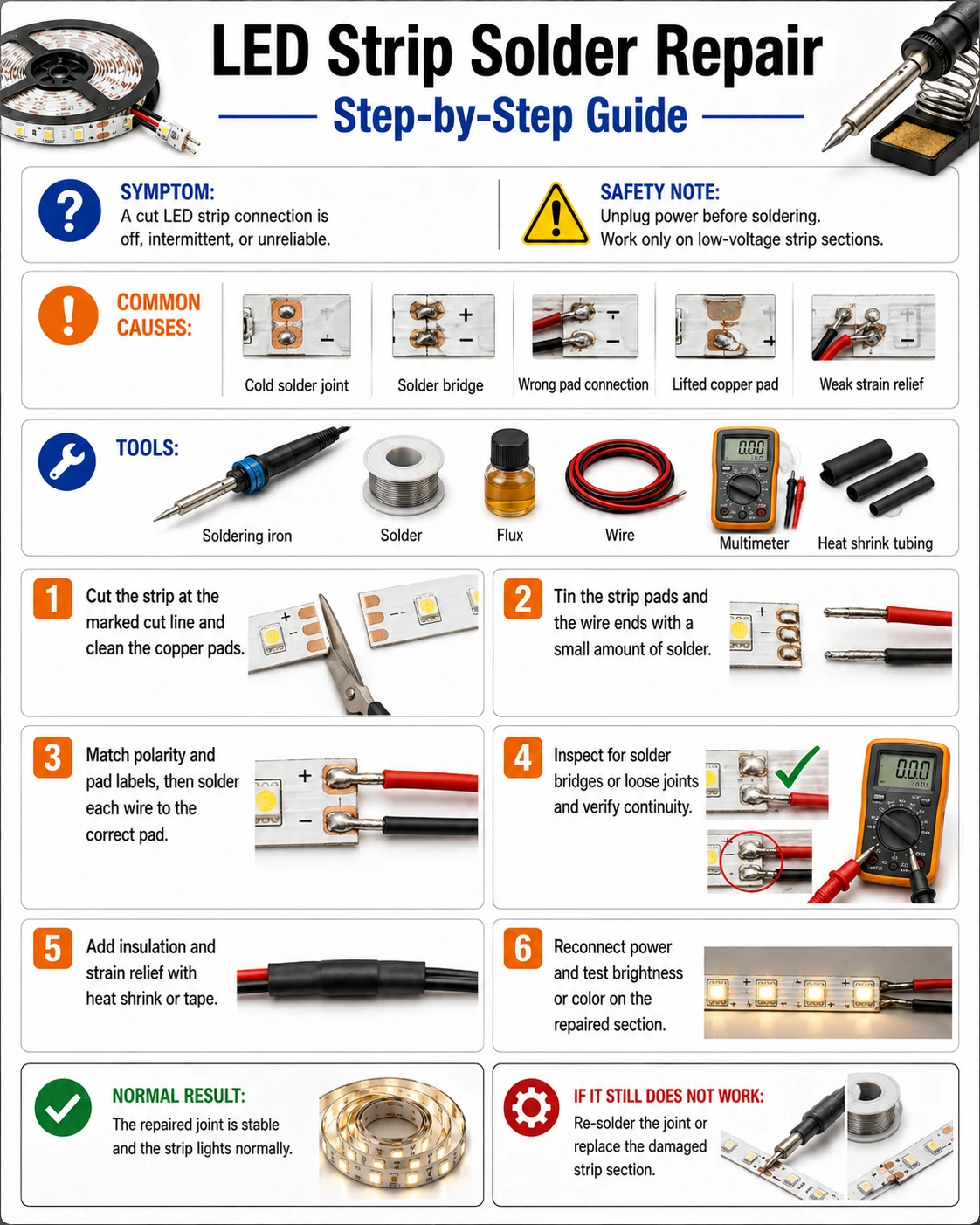
Prepare before testing
- Soldering iron, 30–60 W with a fine tip — set around 320–350 °C; hotter and brief beats cooler and slow
- Rosin-core solder, 0.8–1.0 mm — thin solder doses easily on small pads; no extra flux needed for clean copper
- Craft knife or scalpel — to shave silicone coating off the pads without scoring the copper
- Heat-shrink tubing or liquid electrical tape — insulation that survives flexing, unlike wrapped PVC tape
- Helping-hands clamp or painter's tape — the strip must not move during the two seconds that matter
Solder in a ventilated space and wash hands afterwards. The strip must be fully disconnected — soldering a live 12 V rail welds the tip and sprays solder.
Check these areas first
- Joint needed at a shortened segment. once cut past its connector tab, a strip can only be joined by solder
- Clip connector damaged the pads. repeated clipping scrapes copper until clips no longer grip; solder still works on what remains
- Broken factory joint. the lead-wire joint at the strip head carries full current and fatigues first
- Corner and channel routing. soldered wire bridges make cleaner 90° turns than folding the strip
Diagnostic procedure
The sequence is fixed: cut clean, expose copper, tin both sides, join fast, inspect, then insulate. Skipping the tinning step is what makes joints take too long and pads lift.
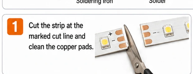
Cut exactly on the marked line
The printed cut line is the only place both halves keep a full set of pads. Use sharp scissors in one motion — a ragged or angled cut leaves half-width pads that overheat instantly. On waterproof strips, cut through the casing squarely so the seal can be rebuilt over a flat face later.
Shave the coating back to bare copper
On coated or waterproof strips, slide a blade flat along the pad surface to lift the silicone off the copper, exposing three to four millimeters. Scrape gently until the pads are bright. Any coating left behind boils under the iron and produces the classic gray, grainy joint that fails in a week.
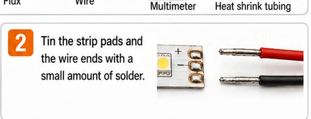
Tin the pads and the wire ends first
Touch the iron to each pad for about a second and flow a small dome of solder onto it; do the same to each stripped wire end. This is the step that makes the final joint fast — two pre-tinned surfaces need only a touch to fuse, instead of long contact while cold metal soaks up heat.
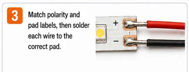
Join each wire with a one-second press
Lay the tinned wire on the tinned pad, press the iron on top until both solder domes flow together — about one second — then lift the iron and hold the wire still while the joint sets. Match wire colors to pad markings; on RGB that order is typically +12 V, R, G, B, and on addressable strips power, data, ground.
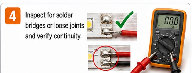
Inspect for bridges and tug-test
Under a magnifier, check the gaps between pads for solder whiskers — on a four-pin strip the pitch is small and a bridge between +12 V and a channel pad lights one color permanently or shorts the rail. Then pull each wire firmly. A joint that survives a deliberate tug will survive installation.
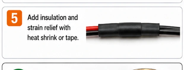
Insulate and rebuild waterproofing
Slide heat-shrink over the joint area or paint it with liquid tape, covering all exposed metal. On outdoor strips, restore the seal: silicone sealant packed into the cut end of the casing or an adhesive-lined shrink sleeve over the whole joint. Only then reconnect power and run all colors at full brightness.
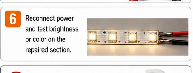
Reading a joint that did not work
One color missing after repair means that channel's joint is open or bridged — reflow it alone. All colors dead means the supply rail joint failed, or the two halves were joined with the arrow directions opposed on an addressable strip. A joint that worked for a day and quit is almost always a cold joint: it looked dull and grainy rather than shiny when made. Reflow with fresh solder rather than adding more on top.
Know the alternative
For a one-off join on undamaged pads indoors, a quality clip connector is honestly fine and reversible. Solder wins when pads are short, current is high, the run flexes, or the joint lives outdoors. If you find yourself soldering the same strip in a fourth place, the strip itself is the problem — spend the evening replacing it, not repairing it.