
Sharp edge or gradual fade — two different faults
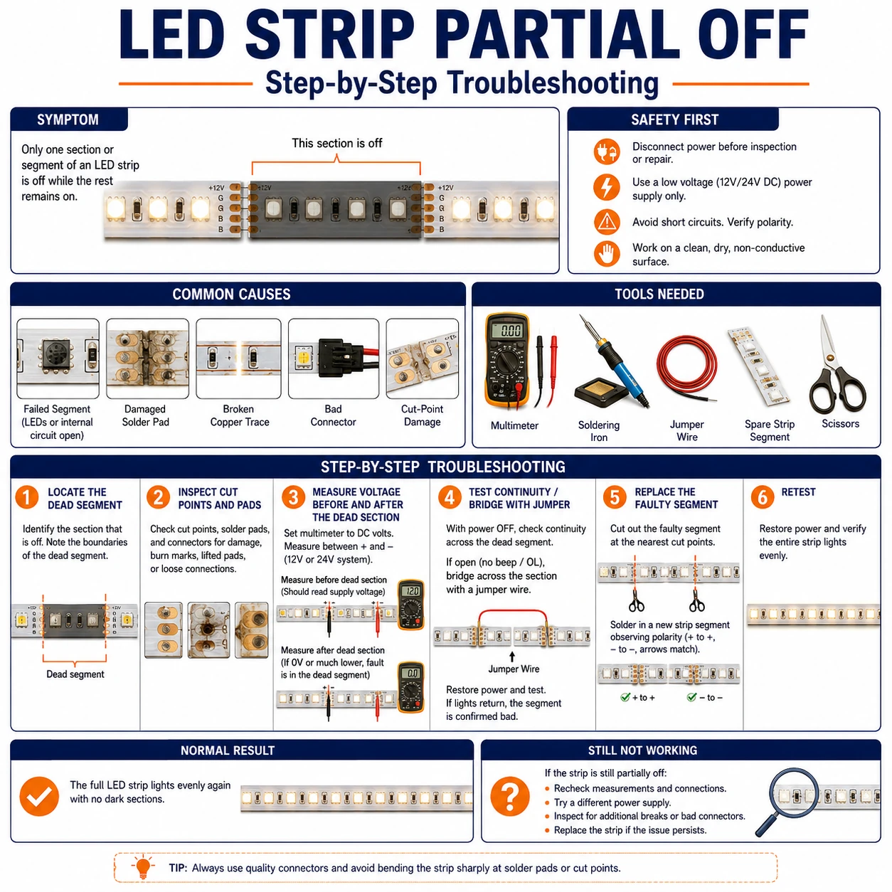
Walk the strip and find where good light ends. If the last lit LED is at full brightness and the next one is completely dark, electricity stops at that line: a cracked solder joint, a failed mid-run connector, or on addressable strips a single dead IC that blocks data to everything downstream. Everything about that fault is local, and the repair is measured in centimeters.
If instead the strip slides gradually from bright white to dim and reddish over its length, nothing is broken at all. Copper traces have resistance; a long run fed from one end simply cannot hold voltage at the far end, and blue LED dies dim before red ones, which is why the tail turns warm-colored. That is a design problem — solved with thicker feed wire, a shorter run, or power injected at the far end — not a defect you can solder away.
Prepare before testing
- Digital multimeter — to read voltage at the head, the boundary, and the tail under full load
- Sharp scissors and spare clip connectors — for cutting at marked lines and bridging a bad segment
- Length of two-core wire, 18–20 AWG — for a far-end power injection test on long runs
- Magnifier — cracked pad fractures at flex points are nearly invisible at arm's length
Cut only at the marked cut lines and only with power disconnected. On addressable strips, note the arrow direction before cutting — a reversed splice will not pass data.
Check these areas first
- Cracked joint at a flex point. strips bent around corners or repeatedly peeled and restuck fracture pads exactly where the light stops
- Failed mid-run clip connector. solderless clips lose grip on the pad or bite the silicone instead of copper
- Dead pixel IC blocking data. on RGBIC strips one failed chip darkens every LED after it, even though power continues down the rail
- Voltage drop on a long single-feed run. 5 V strips show it beyond about 3 m, 12 V beyond 5 m, 24 V beyond 7–10 m at full white
- Overloaded supply. an adapter at its current limit browns out the far end first — looks like voltage drop but is fixed by a bigger supply
Diagnostic procedure
Identify the boundary type first; it decides whether you are hunting a broken joint or redesigning the power feed.
Run full white and map where light ends
Set full-brightness white, the heaviest load and the clearest failure display. Note whether the transition is a hard edge or a gradual fade, and whether the boundary sits at a connector, a cut-line splice, or mid-segment. Photograph it — the position is your map for every later test.
Measure voltage at head, boundary, and tail
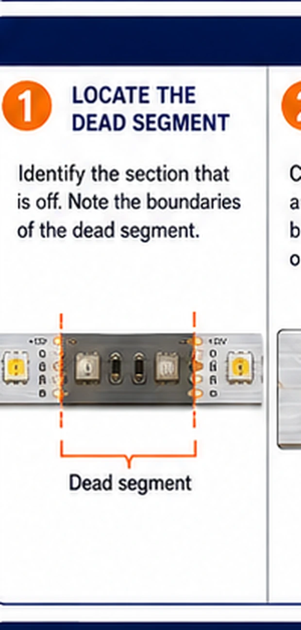
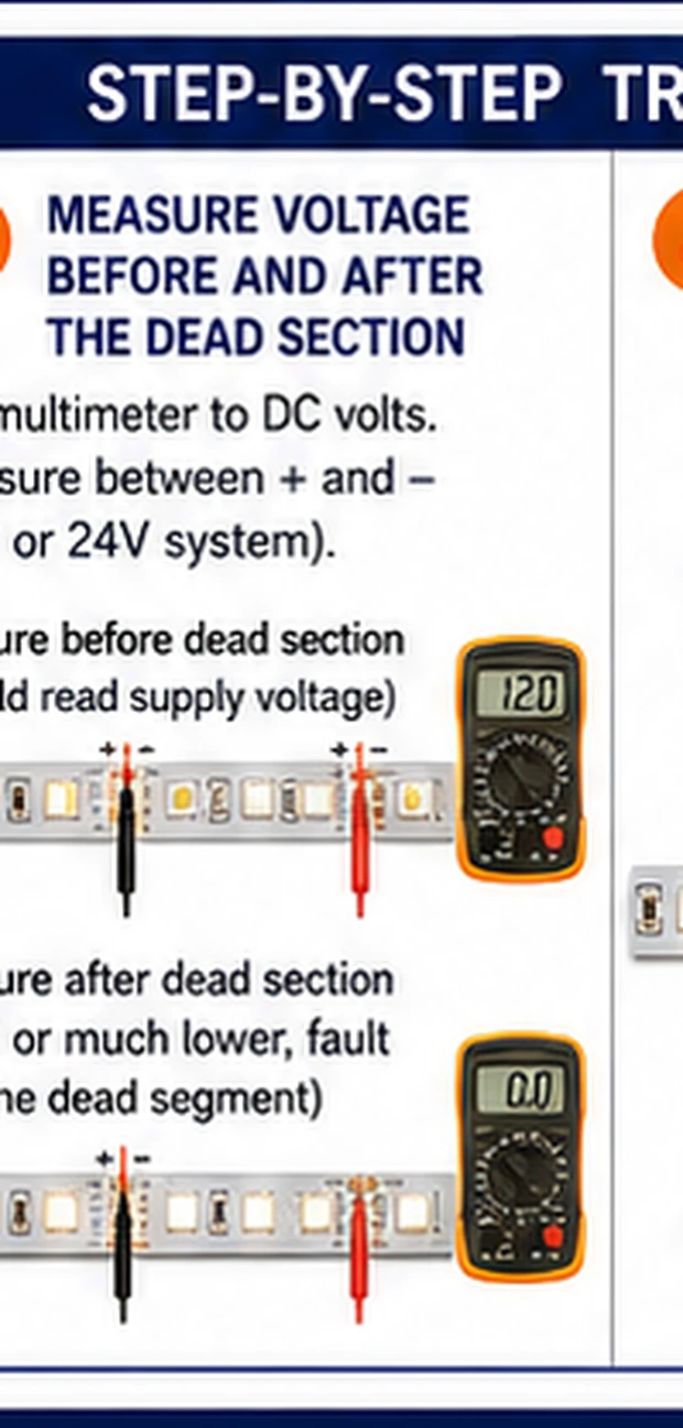
With the strip loaded, read DC voltage at the first pads, at the boundary, and at the far end. Full voltage at a dark section's pads means power arrives but LEDs or data do not use it. A tail reading more than ten percent below the head confirms voltage drop.
Inspect pads and copper at the boundary
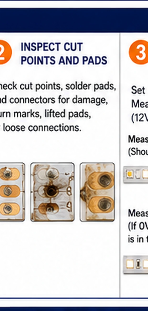
Examine the last working joint under magnification. Look for a hairline crack across a pad, green corrosion under the solder mask, or a clip whose teeth sit on coating rather than copper. Gently press the joint while powered — light returning under pressure is a mechanical break confirmed.
Feed the dark section directly
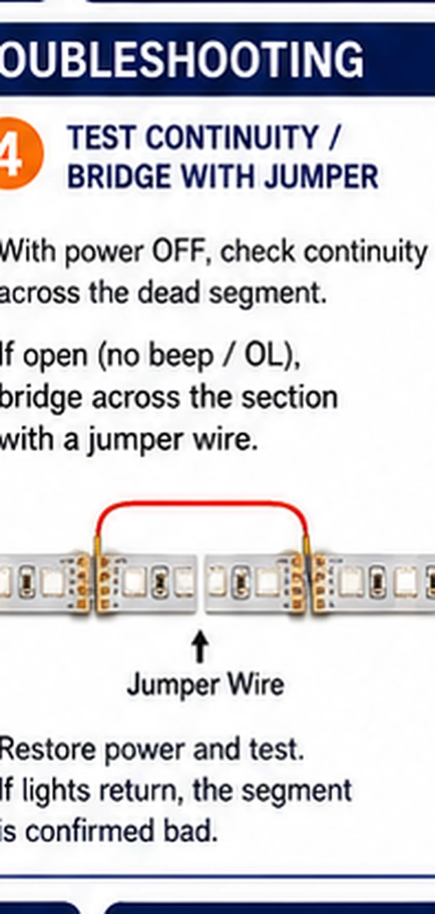
Clip a temporary lead from the supply straight to the dark section's input pads. On an analog strip, light returning proves the break is upstream. On an addressable strip, powered-but-dark confirms a data interruption at the boundary IC instead.
Check data direction after any splice (RGBIC)
If the strip has ever been cut and rejoined, confirm the arrows on both sides of every splice point the same way, and that the data pad maps to data — a splice rotated 180 degrees powers up but passes nothing. Re-make any suspect splice with the arrows aligned.
Bridge or replace the failed segment
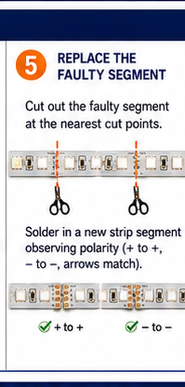
Cut at the marked lines either side of the fault, then either solder in a matching replacement segment or bridge the gap with a four-wire jumper. Match voltage, LED type and IC family exactly on addressable strips — a mismatched segment will light wrong or break data again.
The tail-dim fix is electrical, not surgical
When the diagnosis is gradual fade, fix it with copper, not solder. Three options in rising order of effort: shorten the run or split it into two runs each fed from the supply; replace thin bell-wire feeds with 18 AWG or heavier; or inject power by running a pair of wires from the supply directly to the strip's far end so current enters from both ends. Injection halves the effective run length and is the standard cure for anything over five meters at 12 V.
A quick sanity check before rewiring: if the tail brightens noticeably when you drop the whole strip to 50% brightness, drop is confirmed — the effect scales with current, which is exactly what resistance does.
When segment surgery stops being worth it
One splice is routine; three splices in one strip mean the strip is failing systemically — usually corrosion or fatigue along its whole length — and further patching chases a moving target. Replace the run and keep the old strip as a segment donor for future repairs of the same model.