
Make the controller testify, channel by channel
An RGB controller is a switchboard: one common power rail and a switched return per color channel. Commanding pure red closes the R channel's switch; a meter between common and R should register the change. Channel by channel, the controller either demonstrates working outputs — moving the suspicion to wiring and strip — or shows a channel that never responds, which is a verdict in one reading.
One instrument caveat keeps the readings honest: controllers dim by PWM, switching the channel thousands of times a second, and a multimeter reports the average of that chopping. Half brightness reads roughly half the rail voltage — not because the voltage halved, but because the duty cycle did. The averages are exactly what makes dimming testable; they just must not be mistaken for a failing rail.
Prepare before testing
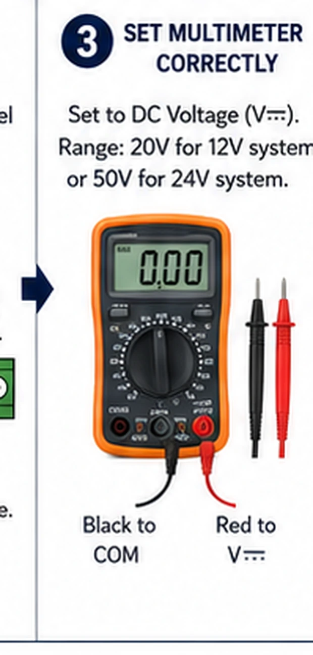
- Digital multimeter — DC volts, on a range above the system voltage; averaging behavior on PWM understood
- The controller's remote or app — the test needs commanded pure colors and deliberate brightness moves
- Fine probe tips or pin adapters — output terminals on small controllers are close-pitched; slipping probes short neighbors
- Paper for a readings table — channel × color-command × brightness — the record is the diagnosis
Low-voltage work throughout, with one care: keep probe tips from bridging adjacent output terminals — a slip shorts a channel through the meter's tip and can genuinely damage the controller being exonerated.
Check these areas first
- Verdict needed before spending. controller and strip replacements each cost real money; one reading spends neither
- One color missing. a channel that never switches — controller output stage, or the strip's channel line
- Dimming misbehavior. brightness steps that jump or stall show in the averaged numbers immediately
- Post-repair verification. after splices and re-wiring, output readings prove the controller before the strip goes back up
- RGBW confusion. the white channel's separate rail and wiring generate their own family of misdiagnoses
Diagnostic procedure
Prove the input, then walk R, G, B with pure commands, exercise the dimmer, and only then compare against the strip's behavior — the order that turns readings into a verdict.
Verify the controller's input first
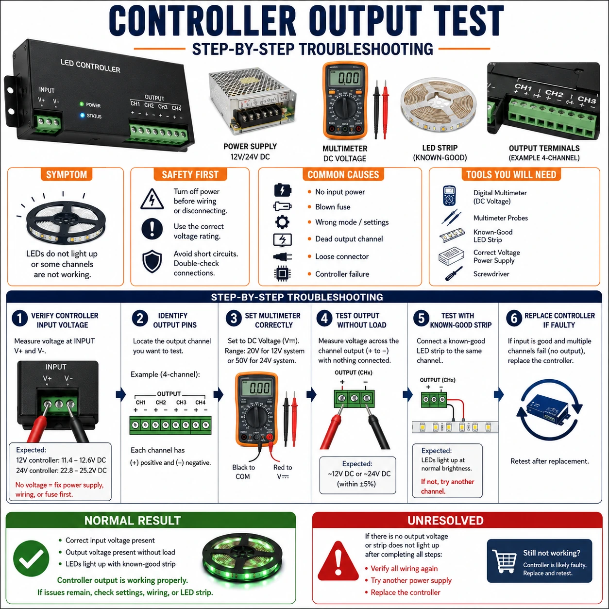
Meter the controller's supply input at its terminals: the system's rated voltage, stable. An undervolted or sagging input makes every output reading meaningless — the controller may brown out mid-test. Input wrong: stop here and fix supply first (its own guide). Input right: everything that follows is attributable to the controller itself.
Command pure red and read the R channel
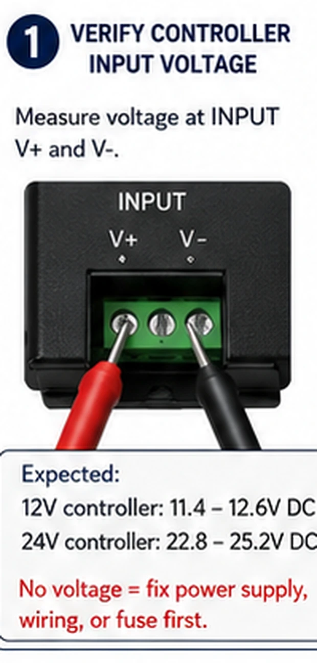
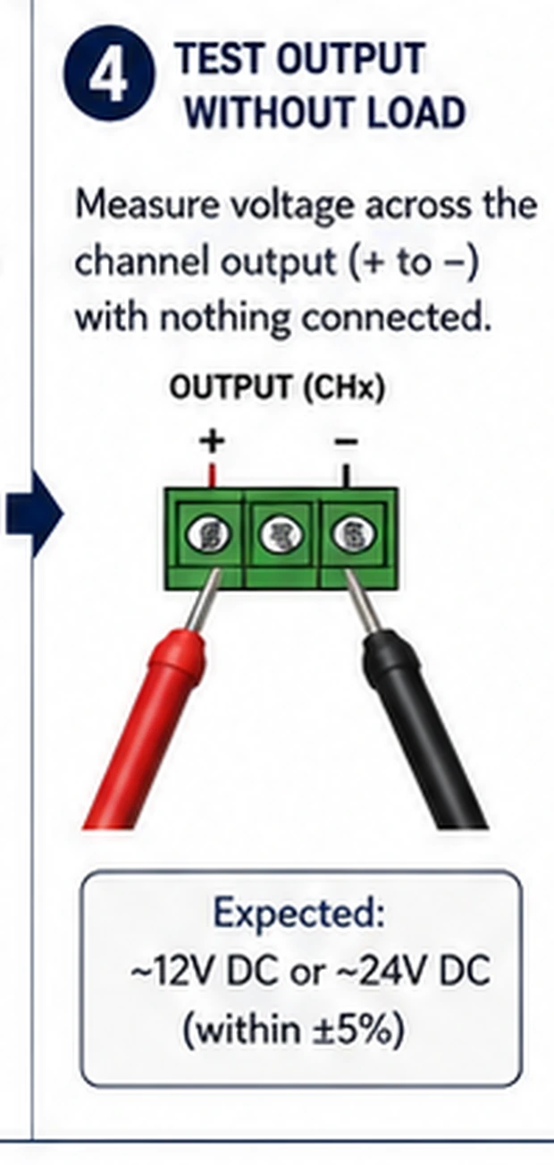
Set 100% red via remote or app. Meter between the common rail and the R output: the reading should move decisively as red switches on — approaching rail voltage on common-anode systems at full duty. Record the number. Then command black/off and confirm the reading collapses. A channel that never moves has already delivered a verdict.
Repeat for green and blue
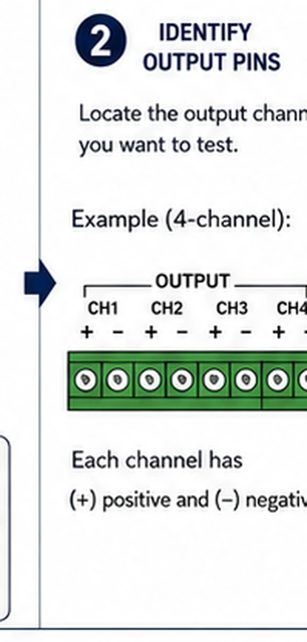
Same procedure per channel: pure green, read G; pure blue, read B; each against common, each at full brightness, each recorded. Consistency across channels is the point — three channels reading alike say the output stage is healthy; one silent or half-voltage channel names the fault precisely.
Exercise the brightness slider
Hold one color at pure and walk brightness 100% → 50% → 25%: the averaged reading should track downward in sensible proportion. Jumps, stalls or a floor where the number stops responding expose dimming-stage faults — and explain the 'flickers at low brightness' complaints that full-power tests never reproduce.
Compare the verdicts at the strip
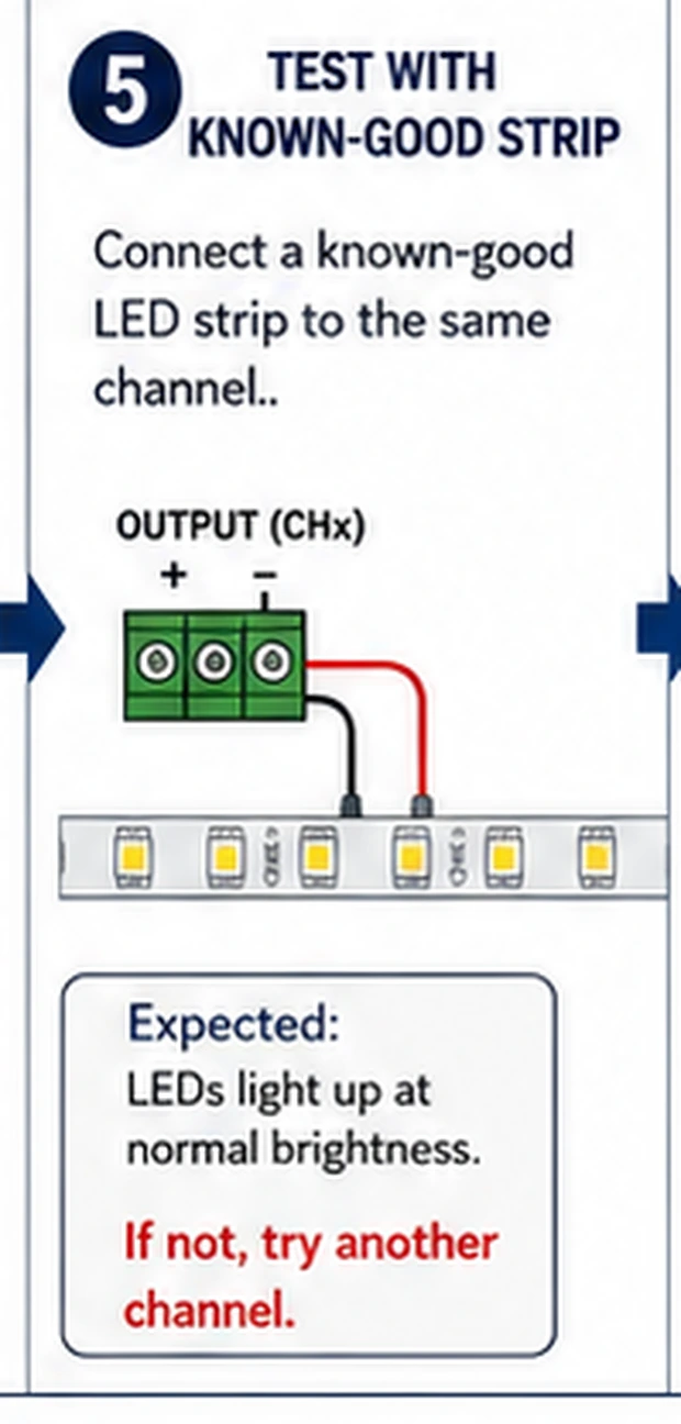
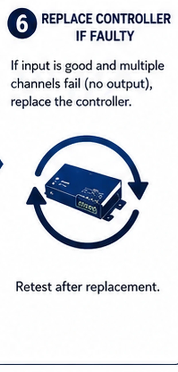
Now reconcile with what the strip does. Outputs healthy but the strip dark or wrong-colored: the fault moved downstream — connector seating, wire order, or the strip's own channels (their guides take over). Outputs dead on a channel the strip also lacks: controller convicted, replacement justified by evidence rather than folklore.
Handle RGBW's extra channel properly
On RGBW systems, repeat the walk for the W terminal with a pure-white command — remembering many controllers drive white as a separate channel, not as R+G+B. A missing white with healthy RGB is the W channel or its wiring, and a four-pin RGB controller pressed into RGBW service will never produce it: the fifth conductor needs a fifth output.
What the averages can and cannot say
A multimeter's average is a faithful proxy for duty cycle, which is why the brightness walk works — but it cannot see PWM frequency or waveform shape. Two controllers can read identical averages while one flickers visibly on camera because it chops at a low frequency. When flicker-on-camera is the actual complaint, the meter narrows the field (rail and channels healthy?) and then hands over to the phone-camera test in the flicker guide, which sees the frequency the meter averages away. Using each instrument for what it measures keeps both honest.
Making the controller test routine
The output test earns a place in three routines. Before condemning any strip: five minutes of readings prevents the classic double purchase. After any splice or connector repair: prove the controller side, then power the strip knowing which half is certified. And when buying used or unbranded controllers: a bench test with a meter and a short sacrificial strip segment reveals dead channels and dimming floors before installation buries the evidence behind trim. A small readings table taped inside the controller box turns next year's fault into a comparison instead of an investigation.