
Two choices decide the whole install
An ACC-switched feed means the lights die with the key — no timer settings, no battery anxiety. The safe way to find one is at the fuse box, using a fuse-tap adapter in a position that measures live at ACC and dead at key-off, and that serves a non-critical convenience circuit. The cigarette-lighter and accessory-socket fuses are the classic candidates; anything labeled for airbags, ABS, engine or lighting control is off the table regardless of its switching behavior.
Ground quality matters as much as the feed. Modern cars are a patchwork of coated panels, adhesives and aluminum, and a randomly chosen screw often grounds nothing. The factory's own designated ground bolts — bare studs with existing ring terminals, usually under the dash or at the kick panel — are the only first-choice answer.
Prepare before testing
- Digital multimeter — voltage for the state tests, continuity for ground verification
- Fuse-tap adapter with its own fuse — adds a circuit without cutting any factory wire
- Vehicle fuse-box diagram — owner's manual or the lid label; identifies each position's job
- Ring terminals and crimper — a proper crimped ring beats any wrapped-wire ground
- Zip ties and split loom — routing away from pedals, hinges and heat is part of the electrical job
Never pierce factory insulation with a test light, and never tap circuits serving airbags, ABS, or engine management. The fuse tap must carry its own fuse rated for the kit.
Check these areas first
- Why not just any fuse. safety-critical circuits share fuses; a fault in your kit must never be able to darken ABS or airbags
- Why ACC and not always-hot. an always-hot feed leaves the controller drawing standby current for weeks of parking
- Why the factory ground stud. coated and bonded panels read as metal but conduct poorly; factory studs are certified low-resistance points
- Why measure under load. an ACC feed can read 12 V open-circuit yet sag through a corroded path once the kit actually draws current
Diagnostic procedure
Identify candidates on paper, verify them with the meter across key states, then prove the ground and the loaded voltage before tidying the harness.
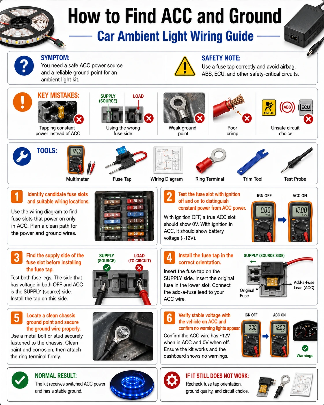
Shortlist fuse positions from the diagram
Read the fuse-box legend and list convenience circuits — accessory socket, rear socket, infotainment accessories. Note each candidate's factory fuse rating; the tap must reinstall that same fuse plus your kit's own. Rule out anything safety-related no matter how conveniently it is placed or labeled.
Test each candidate across three key states
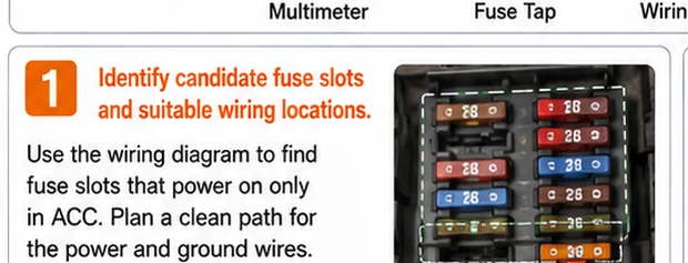
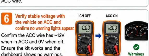
Meter the candidate's test point against ground with the key off, at ACC, and engine running. The right position reads near 0 V off and about 12 V at ACC and running. Positions live in all three states are always-hot; positions live only when running are ignition-switched — usable, but the lights will need the engine.
Determine the fuse position's supply side
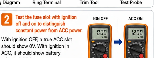
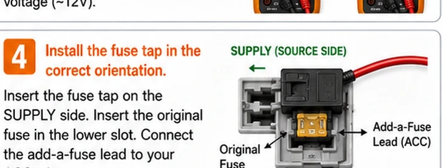
Pull the candidate fuse and measure both exposed terminals at ACC: the one still showing voltage is the supply side. Fuse-tap adapters are directional — installed backwards, your kit's current bypasses the factory fuse. Orient the tap so the added circuit hangs off the supply side through the tap's own fuse, following the adapter's diagram.
Choose and prepare the ground point
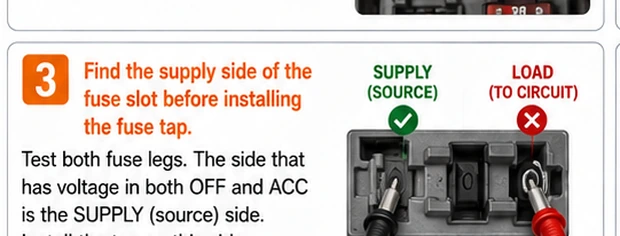
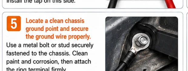
Find a factory ground stud — look for existing ring terminals on a bare bolt at the kick panel, under the dash, or on the seat-rail crossmember (never the seat-belt or airbag anchors). Remove surface rust to bright metal, add your crimped ring terminal, and torque the bolt snug so the stack cannot rotate.
Verify voltage under real load
With the kit connected and running at full brightness, measure at the controller's input: supply pin to your new ground. Compare against battery voltage — more than about half a volt lower means resistance in your feed or ground path; find the corroded or loose link now, not after weeks of mystery flicker.
Route, protect, and label the harness
Route the new wiring away from pedal travel, seat rails, hinge pinch points and heater outlets, sheathed in split loom, tied so nothing hangs. Put a written label on the fuse tap — circuit name and kit rating — so the next person servicing the fuse box (possibly you, in two years) knows what the extra tap is.
The three-state readings that settle every feed question
Every candidate circuit is fully described by three numbers: voltage at key-off, at ACC, and with the engine running. ACC-switched shows 0 / 12 / 12-14; always-hot shows 12 / 12 / 12-14; ignition-only shows 0 / 0 / 12-14. Nothing else needs guessing, and no wire needs piercing — the fuse terminals expose every circuit safely. Take the ten minutes to build this small table before committing the tap; it is the difference between an install and an experiment.
What standby draw actually costs
A controller left on an always-hot feed typically idles at 10–30 mA keeping its radio awake. Against a healthy 60 Ah battery that is trivial for a weekend but real for long parking: 20 mA is roughly half an amp-hour per day, and a month of airport parking plus a cold snap can push an older battery below cranking threshold. ACC switching makes the whole question disappear, which is why it is worth the extra half hour at install time.